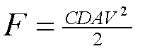
Drag forces on an arrow pile, shaft and fletchings are dominated by inertial forces. The basic inertial drag equation used to calculate drag force on an arrow travelling
through the air is as presented where 'F' is the drag force, 'D' is the air density, 'C' is a drag coefficient, 'A' is the object area and 'V' is the air velocity normal to the surface.
The drag coefficient is a fudge factor which takes into account the complicated
bits like shape and surface characteristics. For a cylinder, like an arrow
shaft, the theoretical value is around 1.2. The velocity is the total net
velocity which comprises the effects of the arrow's travel through the air,
arrow rotation, arrow vibration and any wind. You need to calculate the drag force based on
this total velocity and then as required resolve the drag forces in different
directions. You cannot calculate the drag forces in different directions
and add the components together to give a total drag force (the air can't
be flowing over the arrow shaft in several different directions at the same
time!).
To see where the inertial drag equation comes from suppose you have a fluid flow of speed S and density D impinging on a
body surface of area A at an angle a.We need to take for granted that momentum is mass times velocity and that force is
equal to the momentum change per second. (Force, Velocity and Momentum are all vector quantities).
The mass of air hitting the surface A per second "M" is equal to:-
D*A*S*Sin(a)
The velocity of the air flow at 90 degrees to the surface A "V" is equal to:-
S*Sin(a)
The impinging momentum/second of the air flow on the surface A is equal to M*V. Part of this momentum will be transferred
to the body. Say a fraction X s transferred. then the drag force F on the surface area A is equal to X*M*V. If we define X as
0.5*C then the drag equation becomes 0.5*C*M*V i.e.
F = 0.5*C*A*D*(S*Sin(a))^2
Example Calculation of Drag on an Arrow
There are two drag effects on an arrow, drag that moves the arrow and drag that rotates an arrow. This example only
considers the drag that moves the arrow. To simply things (a lot) were going to assume that the arrow has a parallel
shaft, the arrow is not vibrating and that the arrow is not fishtailing/porpoising. Drag effects on the fletchings
are also ignored. Drag effects are only going to be considered in two dimensions instead of the actual 3.
The arrow is assumed to have the following properties:
Length (L) 0.75 metres
Diameter (d) 0.006 metres
FOC (F) 16%
Speed (S) 50 metres/second
Pitch angle (P) 2 degrees
Total mass (M) 0.018 kilograms
Drag Coefficients Pile = 0.4 Shaft = 1.2
Air density (D) = 1.2 kilograms/cubic meter
Pile Drag
In the drag equation above the velocity 'V' is not (as it sometimes seems to be taken to be) the arrow speed but the speed of the airflow at a right angle to the arrow surface. So for the Pile V = S Cos(P) = 49.97 metres/sec.
[Query 1: how can you talk about the airflow being at a right angle to a pointed shape?
Well the actual effect of the pile shape is include in the value of the drag coefficient and the drag coefficient is based on the shape being symmetrical to to the air flow i.e. along the arrow shaft axis.]
In the drag equation the area 'A' is the frontal exposed area of the body (the area the airflow hits) i.e. the cross sectional area of the shaft so
A = Pi * diameter squared/4 = 0.0000283 square metres
Note that this is only true if the pitch angle is small. With a large angle the area of pile that the airflow will hit will change making life complicated.
The drag force on the pile (Fp) is therefore equal to:-
Fp = 0.5 * 1.2 * 0.4 * .0000283 * 49.97 * 49.97 = 0.017 Newtons
Force is vector, it has direction as well as 'amount of'. The direction of Fp is assumed to be along the axis of the arrow.
[Query 2: Broadhead planing is a big issue so for sure the pile drag direction isn't along the arrow shaft axis?
True it isn't, but for a 'target arrow' pile the direction is fairly close to the shaft axis as long as the pitch angle is small. It's an approximation were making]
Shaft Drag
The drag area of the shaft is its length multiplied by its diameter. The fact that the shaft is curved is handled by
the drag coefficient.
A = Ld = 0.75 * 0.006 = .0045 square meters
The air velocity at a right angle to the shaft is given by:-
V = S Sin(P) = 1.745 metres/second
The drag force on the shaft (Fs) is therefore equal to:-
Fs = 0.5 * 1.2 * 1.2 * .0045 * 1.745 * 1.745 = 0.01 Newtons
The direction of the drag force is at a right angle to the shaft. The reason for this is that the air can't flow
through the shaft. It is only the air flow momentum at 90 degrees to the shaft surface that is transferred between air
and arrow (bearing in mind that frictional effects are being ignored as they are negligible in comparison).
Total Arrow Drag
The total drag on the arrow that moves it is the sum of the pile drag and the shaft drag. Because these drag forces are vectors they have to be added vectorially. In this case as the two drag forces are at 90 degrees to each other the total drag force Ft is given by:-
Ft = SQRT(Fp*Fp + Fs*Fs) = SQRT(0.017*0.017+.01 *.01)= 0 .0197 Newtons
The direction of the total drag force in terms of the angle to the shaft axis (Fa) is given by
Tan(Fa) = Fs/Fp = 0.01/0.017 which gives Fa as 30 degrees.
The arrow is therefore accelerated at .0197/0.018 = 1.09 metre/second squared in a direction at 30 degrees to the
shaft axis (towards the nock end).
Drag acceleration of the arrow is sometimes quoted in terms of the 'g force'. To get this you divide the arrow
acceleration by the gravitational acceleration (9.81 metres/sec squared). i.e the 'g force' equals 1.09/9.81 = 0.11g.
Drag Coefficients and Reynold Number
The drag coefficient relates to the fraction of the incident normal momentum in the air flow that is transferred to the
arrow. (e.g a thin smooth cylinder has a (laminar flow) drag coefficient of 1.2 because about 60% (100*1.2/2) of the normal
air momentum goes into the drag force on the shaft. With a flat surface 100% of the normal air momentum is transferred so
the drag coefficient is (2*100/100) = 2). The drag coefficient also includes the effects of the dynamics of the flow over
the arrow (e.g. laminar/turbulent flow). The value of the drag coefficient varies with the Reynolds number of the flow.
The Reynolds number is the ratio of inertial forces to viscous forces in the fluid flow system. It is calculated as
length x velocity/kinematic viscosity.
Once your out of the region where viscosity has a signicant direct effect on the drag (which is the case for an arrow)
then the drag coefficient remains more or less constant with increasing Reynolds number until the nature of the air flow
changes from being laminar to turbulent. At this point there is a significant drop in the drag force which is reflected by
a drop in the drag coefficient. The drop occurs because with turbulence the boundary layer separates later from the body
and the turbulent lower pressure wake is much narrower and hence the drag reduces. Reducing shaft drag by triggering
turbulent flow over an arrow shaft by having a roughened surface has been (jokingly) suggested by the odd archer/aerodynamicist.
The dimples on a golf ball are there to trigger turbulent flow and reduce the drag. A few years ago a someone (nemecek?)
introduced a javelin with a roughened surface to reduce drag by this means. It was quickly banned as there was some risk
that spectators in the third row might get skewered.
With an arrow shaft it's too thin to sensibly put dimples in it and the net overall effect is arguably fairly
marginal. If you get turbulent flow over an arrow, while it reduces the drag it also reduces the lift and the turning moment
from the fletching action so swings and roundabouts prevail. For flight shooting it might make a measureable difference
but for target shooting my opinion is that it's the usual swings and roundabouts and you would get very little difference
in sight mark.
This raises the issue of whether the airflow over an arrow is laminar, turbulent or rather like a swing bowled cricket ball
both in varying forms over its flight. The answer I think is rather similar to the cricket ball. What determines the flow
Reynolds number (and hence the basic laminar/turbulent flow condition) of a free flying arrow shaft are the air speed, the
arrow diameter and the airflow angle of attack (the "nodal alignment" in archery jargon). We're here assuming the arrow has
a smooth surface (no turbulence triggers) and ignoring the arrrow vibration amplitude. If the arrow shaft was at 90 degrees
to the air flow the flow would be over a circular cylinder and would be laminar. The Reynolds number threshold for laminar to turbulent
flow over a cylinder at 90 degrees is around 2 x 10⁵. The actual Reynolds number for flow over an arrow (based on the tyical arrow
diameter
and speed)
is typically around 1.5 x 10⁵ slightly below the laminar to turbulent threshold. However factors like the arrow point or the vibration of the
arrow might trigger turbulence at a lower Reynolds number rather like the seam on a cricket ball is used to trigger turbulence.
To establish whether the boundary layer for the airflow over an arrow is laminar or turbulent you can either a) use direct observation of the
fluid behaviour over the arrow (particle flow or boundary layer separation point) or b) observe the drop in the drag force on the arrow as the
flow goes from laminar to turbulent consequent upon the delayed boundary layer separation. As far as I know so such observation has been made
(but then I'm not aware of anyone making such an observation.). Here is a classic (golf ball) example of the drop in drag resulting
in tripping turbulent behaviour using a dimpled surface.
For the source of the picture and further information see
AerospaceWeb.org
If the air flow was at zero degrees to the
shaft then the flow would be essentially over the "flat" arrow surface and would be turbulent. Between these two extremes
the air flow is over an ellipse where both the chord length and the ellipse eccentricity vary with the air flow attack
angle. Both of these factors determine whether a laminar or turbulent flow condition occurs. As with an arrow the eccentricity
is always less than 1 it's basically the air flow angle of attack which determines whether the boundary layer undergoes
a transition to turbulent flow before separation. With "typical" values of arrow speed and shaft diameter the critical angle
will be somewhere around 2 degrees. If the attack angle is greater than 2 degrees then we probably have a laminar flow
condition, If less than 2 degrees we probably have a turbulent flow condition.
In practice the angle of attack of the air flow on an arrow during its flight varies all over the place. Generally the initial
flow state will be turbulent (unless the initial launch "nodal alignment" exceeds 2 degrees) then as the angle goes through
the 2 degree angle (going up or down) you will get laminar/turbulent flow transitions. As the arrow speed changes this will
effect the critical angle. A drop in arrow speed will decrease the value of angle below which you get a turbulent condition.
As a rough guide as the bow setup gets poorer, the archer's shot gets poorer or the wind speed increases then you will get
a higher proportion of laminar flow occurence during the flight.
The above assumes the arrow shaft is a rigid rod where in reality, at least during the initial part of the flight, the
arrow will have a significant vibration amplitude. This will result in rapid variations in the attack angle and air flow
velocity at any point on the shaft over time on top of that from the nodal alignment. Anybodies guess on the effect of this.
The articles on arrow aerodynamics referenced on the site home page suggest that arrow vibration trips turbulent flow but give no evidence
for the flow being turbulent.
Air flow over the fletchings will generally be laminar. A crumpled front end or raised tape will act as a
turbulence trigger hence the endless advice to keep fletchings in good condition. Occasionally the turbulent
air flow from the shaft will hit one or more fletchings either a because of low attack angle or the fletching is lying
close close to the same plane as the airflow. In either case the fletchings are not doing much anyway so the effect
is minimal.
[ Postscript October 2014: There have been some preliminary investigation recently of arrow aerodynamics including laminar/turbulent flow transitions. Some are
referenced on the home page of this site. The equipment-arrow page of the bibliography will hopefully keep up to date on this topic.]
 The drag coefficient is a fudge factor which takes into account the complicated
bits like shape and surface characteristics. For a cylinder, like an arrow
shaft, the theoretical value is around 1.2. The velocity is the total net
velocity which comprises the effects of the arrow's travel through the air,
arrow rotation, arrow vibration and any wind. You need to calculate the drag force based on
this total velocity and then as required resolve the drag forces in different
directions. You cannot calculate the drag forces in different directions
and add the components together to give a total drag force (the air can't
be flowing over the arrow shaft in several different directions at the same
time!).
The drag coefficient is a fudge factor which takes into account the complicated
bits like shape and surface characteristics. For a cylinder, like an arrow
shaft, the theoretical value is around 1.2. The velocity is the total net
velocity which comprises the effects of the arrow's travel through the air,
arrow rotation, arrow vibration and any wind. You need to calculate the drag force based on
this total velocity and then as required resolve the drag forces in different
directions. You cannot calculate the drag forces in different directions
and add the components together to give a total drag force (the air can't
be flowing over the arrow shaft in several different directions at the same
time!).  The arrow is assumed to have the following properties:
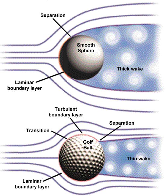 To establish whether the boundary layer for the airflow over an arrow is laminar or turbulent you can either a) use direct observation of the
fluid behaviour over the arrow (particle flow or boundary layer separation point) or b) observe the drop in the drag force on the arrow as the
flow goes from laminar to turbulent consequent upon the delayed boundary layer separation. As far as I know so such observation has been made
(but then I'm not aware of anyone making such an observation.). Here is a classic (golf ball) example of the drop in drag resulting
in tripping turbulent behaviour using a dimpled surface.
To establish whether the boundary layer for the airflow over an arrow is laminar or turbulent you can either a) use direct observation of the
fluid behaviour over the arrow (particle flow or boundary layer separation point) or b) observe the drop in the drag force on the arrow as the
flow goes from laminar to turbulent consequent upon the delayed boundary layer separation. As far as I know so such observation has been made
(but then I'm not aware of anyone making such an observation.). Here is a classic (golf ball) example of the drop in drag resulting
in tripping turbulent behaviour using a dimpled surface.